Eurorack supply
The disaster of Eurorack supply
Short history
At the birth of Eurorack as a generic name for a format of modular synthesizers, there was a then small German company called Doepfer.
Its founder, Dieter Doepfer found convenient to reuse parts of the official Eurorack specification as the mechanical basis for modular synthesizers more compact than the then prevalent Moog format.
Industrial (official) Eurorack is a well-documented specification that encompasses mechanical and electrical aspects of systems used in industries, trains, power plants, hospitals and other high reliability purposes, and is thus more on the costly side of things.
In his attempt at reducing the cost on the electrical side, Doepfer went for a cheap bus-board fitted with headers instead of proper shrouded/boxed connectors with guaranteed orientation
Is there a problem?
Unfortunately, there are several problems with the legacy of Doepfer’s specified Eurorack supply bus.
1. Reversibility
Contrarily to some connectors such as USB-C that can be plugged both ways, the Eurorack connector must be inserted in the proper orientation. If not, supply problems will occur.
This issue must be solved by the module designer by implementing some protection circuitry so that plugging a supply cable the wrong way does not kill the module.
Hopefully, solutions are affordable and easy to implement.
Given the difference in cost for headers versus shrouded connectors, it is a shame to still design and sell bus-boards and modules with unshrouded connectors.
The standard for IDC shrouded connectors dates back to the nineteen-sixties. There is zero excuse for not following it. It specifies the pin numbering and the place of the cable marking on the pin 1 side and the connector shape prevents reverse insertion.
2. “The” supply shorting issue
Here is the main reason behind this whole article.
When defining the supply connector pin allocation, one horrible mistake was done leading to serious consequences.
Adding the wrong way a module to a rack can fry other modules that make use of the 5V rail !
How is that possible? How could a mistake done with one module kill some other(s)?
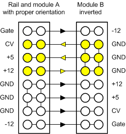
As could be seen in the following drawing, the ground pins of the inverted module become independent from the ground; instead, since they are all joined on the inverted module, they short the 12V and 5V rails (and CV). The 12V supply is sent where there should be only 5V.
Depending on the type and strength of the supply, the resulting voltage on the 5V rail goes somewhere between 7V and 12V, guaranteeing a sure fry of all modules expecting the 5V rail to not be beyond 5V.
Note that a lack of proper protection, can also impact the reversed module! This depends on the module design and if it was actually mounted in the case or left "floating" outside, therefore creating or not an independent path to ground.
Killing the 5V regulator !
Bringing 12V on the 5V rail can kill the passive 5V regulators usually mounted on the busboard.
These chips don't stand the excess backward current or a voltage higher than their normal output voltage.
As a user, what should I take care of?
Be extra cautious with the connector orientation when adding modules with a 16-pin connector.
Some older Doepfer modules are documented as presenting a reversed connector. With a bus-board offering shrouded connectors, you will need a custom inverting cable, in other words, a cable deliberately manufactured the wrong way!
Note that several would-be Eurorack designers provide various wrongly assembled cables:
- Electrically OK cables but with the cable red marking on the wrong side
- Cables with a connector inverted at one end, implicitly with a wrong red marking at some end !
I case of uncertainty, here is a strategy to minimize the risk:
- Don't add a new 16-pin module if there are already 16-pin modules in the rack.
- First, disconnected the supply cables from all your 16 pin modules. Take notes/pictures if some later reinsertion will not be obvious!
- Then connect your newly acquired module alone (alone among the 16-pin ones).
- Only if the new module behaves nicely alone can you reconnect the other ones whose orientation was known and validated.
With this approach, if inserted the wrong way, the new module cannot fry any other.
If you are serious about protecting your investment, buying a dedicated Eurorack cable tester is a good idea. Especially if you are fond of DIY and other hobbyist and handcrafted modules.
As a module designer what should I do?
Never use the 5V rail as a 5V-guaranteed supply.
If the user inverts another module, you'll get more than the expected 5V!
On the other hand, using the 5V rail with a regulator that makes a lower voltage (e.g. 3.3V) from the 5V is fine as long as your regulation circuit (regulator and capacitors) can accept 12V and stand the heat increase resulting from a higher than expected voltage drop.
Possibly do not use pins 7 and 8 in your designs when designing with a 16-pin connector. You still have 4 pins of ground instead of 6, which is plenty.
- This will avoid shorting the 5V and 12V rails in case of connector inversion by the user, thus protecting the user's other modules.
- There still will be a possible short between the 5V and the CV rails which hopefully is unlikely to kill anything.
Could have it be done differently?
If Dieter Doepfer took a few minutes thinking about his supply implementation choices, hundreds of modules premature dead could have been avoided. Many users and manufacturers learned it the hard way.
Various options for a better pin mapping were available. Unfortunately, Doepfer went for the most disastrous choice.
Having the only two positive supply rails being shorted (in case of inversion) means that the usual protecting diodes are helpless.
If only the 5V was put at the end of the connector (pins 15 and 16), everything would be fine. There would be no overvoltage short and the inversion of polarity would be stopped by simple protecting diodes.
It could have been done even better by making the whole connector reversible (à la USB3) where the pin allocation is reversed on the two connector rows. At least, such implementation could have been an excuse for using simple headers without orientation protection.
<\/p>\n
Possibly do not use pins 7 and 8 in your designs when designing with a 16-pin connector. You still have 4 pins of ground instead of 6, which is plenty.<\/p>\n
- \n
- This will avoid shorting the 5V and 12V rails in case of connector inversion by the user, thus protecting the user's other modules.<\/li>\n
- There still will be a possible short between the 5V and the CV rails which hopefully is unlikely to kill anything.<\/li>\n<\/ul>\n
\u00a0<\/p>\n
\n
<\/p>\n
Could have it be done differently?<\/h3>\n
If Dieter Doepfer took a few minutes thinking about his supply implementation choices, hundreds of modules premature dead could have been avoided. Many users and manufacturers learned it the hard way.<\/p>\n
Various options for a better pin mapping were available. Unfortunately, Doepfer went for the most disastrous choice.<\/p>\n
Having the only two positive supply rails being shorted (in case of inversion) means that the usual protecting diodes are helpless.<\/p>\n
If only the 5V was put at the end of the connector (pins 15 and 16), everything would be fine. There would be no overvoltage short and the inversion of polarity would be stopped by simple protecting diodes.<\/p>\n
<\/p>\n
It could have been done even better by making the whole connector reversible (\u00e0 la USB3) where the pin allocation is reversed on the two connector rows. At least, such implementation could have been an excuse for using simple headers without orientation protection.<\/p>\n
\u00a0<\/p>"}}]}]}]}]} -->